|
|
Post by tlr on Nov 21, 2005 12:25:18 GMT -5
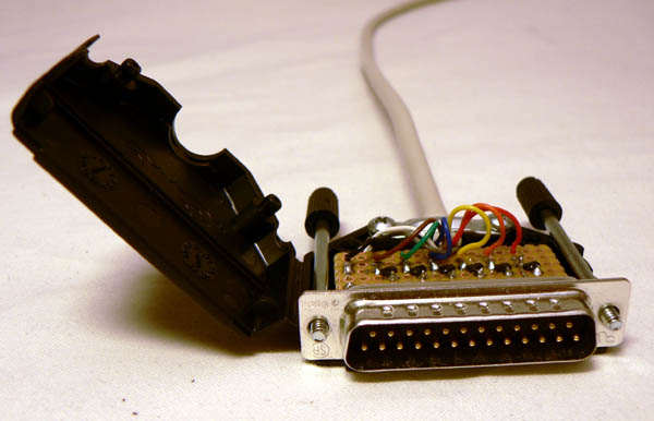
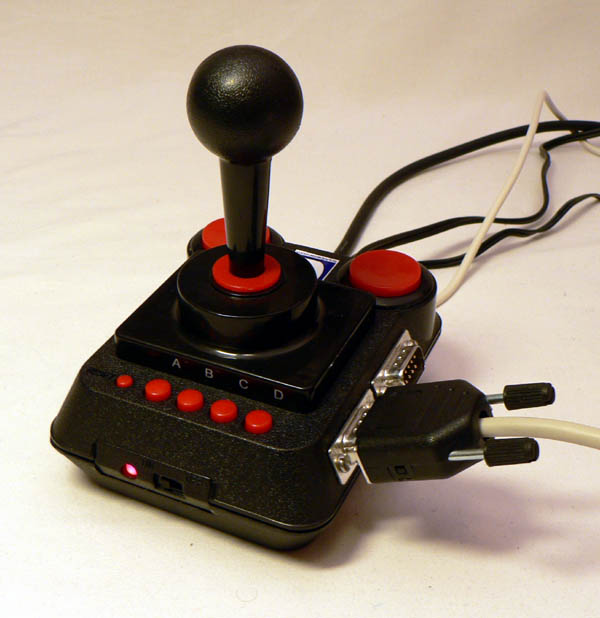
I just finished a transfer cable for connecting my C64 DTV to a PC. It consists of a 5 wire bidirectional connection pluggable into joystick port 1 or 2. An optional reset signal is wired to the POT X line of the joy port so the PC may reset the DTV. I have working transfer software in one direction, but it is very rudimentary at the moment. Will tidy up and optimize tonight.  If anyone is interested I can post more details later on... /Daniel The completed cable:  The insides:  Hooked up and running:  |
|
|
|
Post by Six on Nov 21, 2005 13:05:07 GMT -5
Very nice, this could work on the regular C64 as well, no?
|
|
|
|
Post by tlr on Nov 21, 2005 13:22:00 GMT -5
Very nice, this could work on the regular C64 as well, no? Thanks! Yes it could, but I'm not certain that the 6526's have open-drain outputs, atleast not by default, so maybe the software has to be tweaked a bit to ensure that the C64 won't try to force the signal high. The C64 DTV ASIC has open-drain outputs, so here this is completely safe! |
|
Moloch
Junior Member
 
Posts: 55
|
Post by Moloch on Nov 21, 2005 15:02:22 GMT -5
Nice  Please post more details when you have time. |
|
|
|
Post by David Murray on Nov 21, 2005 15:34:08 GMT -5
Wait.. I thought it had already been tested and determined that the joystick ports on the DTV could not output data, unlike a real C64. So you are saying that the DTV "CAN" in fact output data? If that is so, I can hook up a bunch of shift-registers to the joystick port and control LEDs for my project. Currently I'm using the user-port on my C64 to do that.
|
|
|
|
Post by tlr on Nov 21, 2005 16:18:26 GMT -5
Wait.. I thought it had already been tested and determined that the joystick ports on the DTV could not output data, unlike a real C64. So you are saying that the DTV "CAN" in fact output data? If that is so, I can hook up a bunch of shift-registers to the joystick port and control LEDs for my project. Currently I'm using the user-port on my C64 to do that. I don't know about the V1, but it says in the V2 manual that, among others, JoyA0-A5 / JoyB0-B5 / USR0-7 are bi-dir 5V-tolerant pins with internal pullups. Further down it is stated that all of those are open-collector pins. This is actually open-drain as the process most probably is CMOS, but it works the same way. Besides, if you look in the schematic you realize that atleast JoyA0 must be able to sink current, as this enables the A-D buttons. |
|
|
|
Post by David Murray on Nov 21, 2005 18:09:14 GMT -5
Forgive my stupidity. WHat exactly does "open drain" mean? When I get home from work tonight I'm going to get the multimeter out and write a little code to output data to the joy ports. I've already hacked my DTV so that it has standard joystick ports, so this won't take long at all. But I've not heard this particular term before.
|
|
|
|
Post by David Murray on Nov 21, 2005 23:17:43 GMT -5
Well, I'm not having any luck with outputting anything. I have tried poking address 56322 (which should, I believe be the data direction register for port 2) with zero.. which I think should set it all to output mode. Incidently if I do it with 56323 it locks the keyboard up. Since I know port 1 is combined with the keyboard that would make sense. Anyway, I read my joystick on my DTV fine with 56320 which means there is a mistake in my C64 programmer's reference guide because it shows them backwards. Anyway, I wrote a program to alternate every second sending zero and 256 to the data port there and I held a volt-meter to the port and it never changes. The ports seem to be held high as my meter constantly reads about 3.2 volts comming out of all of the data pins on the joy-port. Hmm.. Let me know if I'm doing something wrong. Otherwise I might need to invest in a Hummer from Radio Shack after all.
|
|
|
|
Post by RaymondDay on Nov 22, 2005 8:21:06 GMT -5
It would be nice if you could get some term. program to work in and out of the joy stick port. You know like a modem port. The USR port has to do a RS232 so maybe the joystick port on the DTV can too.
For a RS232 all you need is 2 lines send and receive. Ground too so 3 lines. I am sure the joy stick port has that. Could it be used like a RS232 then?
|
|
|
|
Post by tlr on Nov 22, 2005 18:04:22 GMT -5
Forgive my stupidity. WHat exactly does "open drain" mean? When I get home from work tonight I'm going to get the multimeter out and write a little code to output data to the joy ports. I've already hacked my DTV so that it has standard joystick ports, so this won't take long at all. But I've not heard this particular term before. Just one google away: hereBasically the output stage is just a transistor that may force the signal low. A resistor is (in this case) connected from the output to Vdd/Vcc. If the transistor is not activated the resistor will pull the signal towards Vdd/Vcc. Reading the registers will show the state of the pin. If the signal is set to '1' the transistor will be inactive, thus enabling an external button or transistor to force the signal low. |
|
|
|
Post by tlr on Nov 22, 2005 18:13:07 GMT -5
Well, I'm not having any luck with outputting anything. I have tried poking address 56322 (which should, I believe be the data direction register for port 2) with zero.. which I think should set it all to output mode. Incidently if I do it with 56323 it locks the keyboard up. Since I know port 1 is combined with the keyboard that would make sense. Anyway, I read my joystick on my DTV fine with 56320 which means there is a mistake in my C64 programmer's reference guide because it shows them backwards. Anyway, I wrote a program to alternate every second sending zero and 256 to the data port there and I held a volt-meter to the port and it never changes. The ports seem to be held high as my meter constantly reads about 3.2 volts comming out of all of the data pins on the joy-port. Hmm.. Let me know if I'm doing something wrong. Otherwise I might need to invest in a Hummer from Radio Shack after all. '1' means output in the data direction registers. You have set all your pins to inputs! Using joystick port 2 for output from basic is kind of tricky. The key scan interrupt routine will write once every interrupt to the output at $dc00 (56320), so you'll have to disable the interrupts for this to work. Using joystick port 1 is easiest. Just do:
10 POKE 56323,255:POKE 56321,<value>
20 GOTO20
and you'll get it. Press Esc/Break to exit, or make your program do POKE56323,0 to restore correct keyboard operation before exiting. All this is much easier to do in assembly language though.  |
|
|
|
Post by David Murray on Nov 22, 2005 22:57:50 GMT -5
Hmm.. But I thought joystick port 1 was tied to the keyboard and that is why most games like to use joystick port 2. So why does the keyboard scan interfere with port 2, but not with port 1? I'm confused. But I'll go try it and see what happens. I haven't wired up port 1 on my DTV unit so I can't test that. But I'll try it on my real C64 and see what happens.
However, this has seriously hampered my thoughts on this idea. If the keyboard scan routine is going to interfere with both joystick ports then I may be screwed for wanting to use the ports as general purpose I/O lines. I realize you could turn the keyboard scan routines off or disable interrupts with the CLI command, but the keyboard will be an essential part of my program. So the user-port on a real C64 still seems far more desirable than the DTV by the look of things.
|
|
|
|
Post by tlr on Nov 23, 2005 16:43:01 GMT -5
Hmm.. But I thought joystick port 1 was tied to the keyboard and that is why most games like to use joystick port 2. So why does the keyboard scan interfere with port 2, but not with port 1? I'm confused. But I'll go try it and see what happens. I haven't wired up port 1 on my DTV unit so I can't test that. But I'll try it on my real C64 and see what happens. Both ports are connected to the keyboard scanning matrix. The pins shared with Joystick port 2 are always used as outputs during keyscan, and the pins shared with joystick port 1 are used as inputs. Both ports will interfere with keyboard scanning. However, this has seriously hampered my thoughts on this idea. If the keyboard scan routine is going to interfere with both joystick ports then I may be screwed for wanting to use the ports as general purpose I/O lines. I realize you could turn the keyboard scan routines off or disable interrupts with the CLI command, but the keyboard will be an essential part of my program. So the user-port on a real C64 still seems far more desirable than the DTV by the look of things. The C64 DTV also has a userport. Most of the pins (all?) seem accessible on the V2. According to the schematic they are connected to configuration pull-ups and pull-downs, so they could be wired to an external port from there. |
|
|
|
Post by David Murray on Nov 23, 2005 17:45:49 GMT -5
full user-port in the DTv2? Doesn't the hummer game sold by radio shack have a version 2 board inside? Does anybody know if it has user-port available?
Also.. since you are working on some transfer software, I guess you've gotten the joy-port to work for that. So is there any good way to use the joystick port for input and output and still be able to use the keyboard too? won't the keyboard scan routine send eroneous data to whatever devices you have connected?
|
|
|
|
Post by Sean Cross on Nov 23, 2005 20:32:58 GMT -5
I did find three pins of the userport on the Hummer game. I've been unable to find joyports, however, so I haven't done much with mine.
I'm sorry, I don't remember which pins they were I found, though I suspect they were in the lower nybble, as the highest number I could peek() was 16.
Now, has anyone found the joyport pins on this game yet? :)
|
|